- All
- Product Name
- Product Keyword
- Product Model
- Product Summary
- Product Description
- Multi Field Search

 English
Views: 0 Author: Site Editor Publish Time: 2026-08-19 Origin: Site


High-density developments increasingly rely on vertical parking solutions, but miscalculating traffic throughput can transform a luxury amenity or commercial necessity into a severe operational bottleneck. Architects, developers, and facility managers often focus on weight capacity and footprint, neglecting the dynamic metric of Vehicles Per Hour (VPH). Underestimating peak-hour traffic leads to street-level queuing, user frustration, and potential zoning or safety compliance failures.
Moving from theoretical specifications to real-world operational throughput requires a strict traffic analysis. This guide breaks down how to calculate true cycle times, evaluate system architectures, and specify a Car Elevator system that aligns with your facility's peak demand.
Table of Contents
Cycle Time Dictates Throughput: True capacity is measured in total cycle time (loading, transit, unloading, and return), not just the mechanical speed of the lift.
The Maximum Load Penalty: Operating a car elevator at its maximum weight capacity (e.g., consistently lifting 10,000-pound vehicles on a 10,000-pound rated lift) can degrade performance and increase cycle times.
System Architecture Matters: Hydraulic systems are cost-effective for low-rise, low-traffic applications, while traction or multi-car systems are mandatory for high-throughput, high-rise demands.
Staging is Critical: Elevator hall sizing and queuing space must be engineered to accommodate at least 50% of the combined maximum capacity of the cars during peak traffic hours.
Theoretical elevator speeds provided by manufacturers rarely reflect real-world throughput. Decision-makers must calculate the full operational loop to determine actual Vehicles Per Hour (VPH). Relying solely on the feet-per-minute (FPM) or meters-per-second (m/s) rating of the hoisting mechanism creates a false sense of capacity. You must account for human behavior, mechanical sequencing, and physical staging on the job site.
A single complete cycle consists of several distinct phases. Each phase adds seconds to the total loop. Missing even one variable skews the entire traffic model. When we evaluate a site, we break the movement down into five specific actions.
Loading/Entry Time: Time required for a driver to align, enter the cabin, and secure the vehicle. Cabin width, approach angle, and lighting heavily influence this metric. A steep ramp leading directly to the shaft doors forces drivers to crawl, adding heavy delays.
Door Operation: Time for heavy-duty safety doors to open and close at both ends of the journey. Industrial bi-parting doors move slower than standard passenger elevator doors due to their sheer mass and safety sensor requirements.
Transit Time: The mechanical travel time between floors. This includes the variable frequency drive (VFD) acceleration curve, top speed, and the deceleration curve required to level the platform perfectly with the landing.
Unloading/Exit Time: Time for the vehicle to safely exit the cabin and clear the immediate staging area. If the exit aisle is narrow, drivers hesitate, holding the elevator at the landing.
Return/Reset Time: Time for the empty elevator to return to the primary loading floor to accept the next vehicle.
To establish a realistic traffic model for your building, follow this exact sequence of calculations:
Determine the mechanical transit time for a one-way trip based on the manufacturer's FPM rating and the total vertical rise of the shaft.
Add the door opening and closing times for both the departure and arrival landings.
Estimate the human factor for loading and unloading based on the staging area's turning radius (typically 15-25 seconds per action).
Sum these values to find the total time for a loaded trip.
Calculate the empty return trip time (transit plus door operations).
Add the loaded trip time and the empty return time to establish the total cycle time in seconds.
Divide 3,600 (seconds in an hour) by the total cycle time to find the maximum theoretical VPH per shaft.
Apply a 0.80 efficiency multiplier to account for real-world variables like dropped keys, sensor trips, and driver hesitation.
Cycle Time Breakdown and Impact Factors
Operational Phase | Estimated Time (Seconds) | Impact Factor on Throughput |
|---|---|---|
Vehicle Approach & Entry | 15 - 25 | High (Depends on driver skill and approach angle) |
Door Closing Sequence | 8 - 12 | Low (Fixed mechanical speed) |
Vertical Transit (2 Floors) | 20 - 40 | Medium (Depends on drive type and load) |
Door Opening Sequence | 8 - 12 | Low (Fixed mechanical speed) |
Vehicle Exit & Clearance | 10 - 20 | Medium (Depends on exit path layout) |
Empty Return Transit | 15 - 30 | Low (Often faster without payload) |
In grouped systems, handling capacity depends heavily on the time interval between two subsequent cars arriving at the loading bay. This interval dictates the average system-wide cycle time. Adding a second shaft does not strictly double your throughput if the staging area cannot feed both shafts simultaneously. Traffic analysis for multi-car systems must map the synchronization of dispatch algorithms. A longer cycle time in one shaft creates a cascading delay across the group, especially if vehicles are blocking the primary access lane while waiting for a specific door to open.
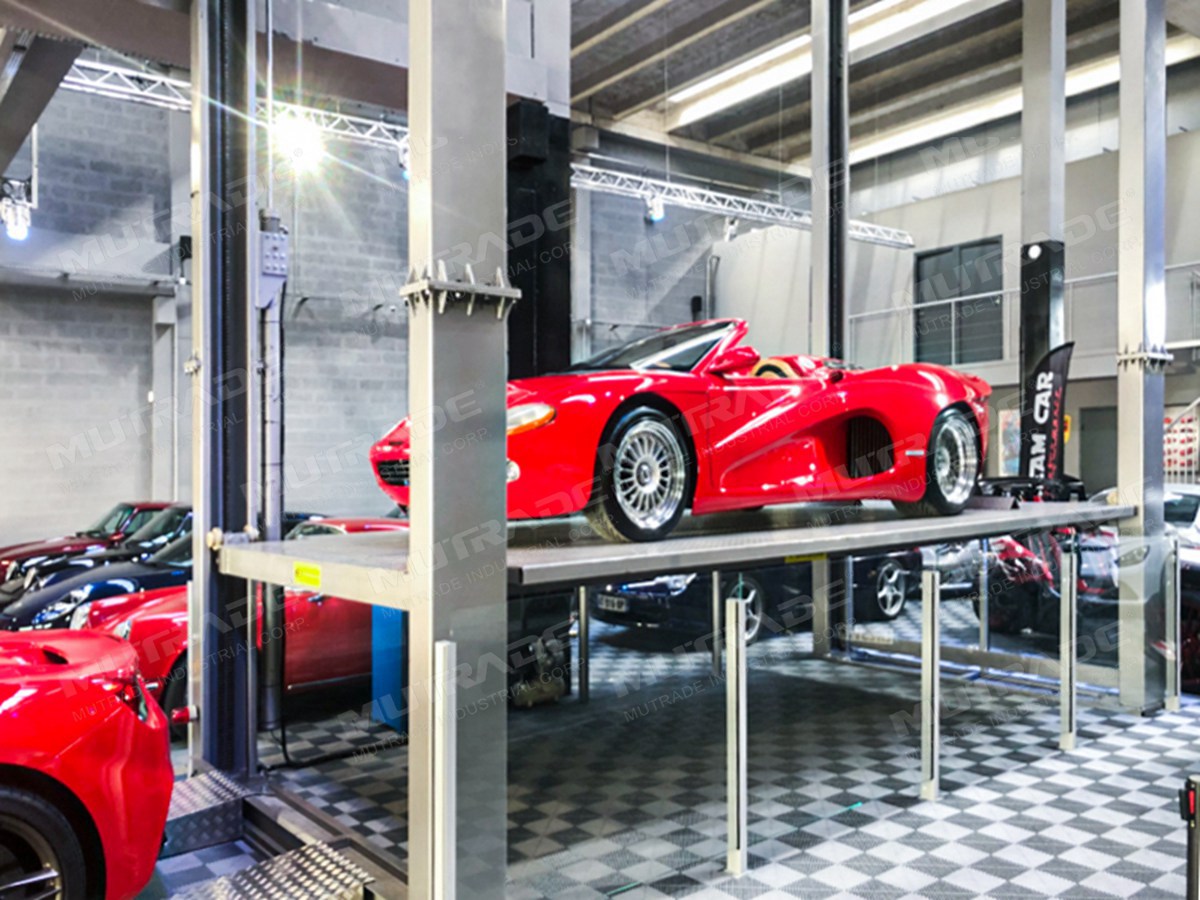
Different mechanical systems offer vastly different traffic flow profiles. Selecting the wrong drive mechanism limits your maximum cycle efficiency regardless of how well you design the building. We see projects fail in the commissioning phase because the specified drive cannot handle the actual daily duty cycle.
Hydraulic systems utilize a pump to push fluid into a cylinder, raising a piston attached to the platform. They dominate the low-rise market due to their straightforward installation and lack of overhead machine room requirements.
Throughput Profile: These systems feature slower transit speeds. They are best suited for low-rise applications involving two to four stops. They fit low-to-medium traffic environments perfectly, such as private residential garages or small boutique dealerships.
Capacity Realities: Most standard commercial hydraulic platforms are engineered to support a baseline of approximately 7,000 pounds per vehicle. While manufacturers can upgrade them, hydraulic fluid dynamics dictate a harsh reality. Heavier loads increase pressure demands, which can marginally impact lifting speed. Fluid viscosity changes based on temperature and continuous use. During a heavy morning rush, the hydraulic oil heats up, which can alter leveling accuracy and extend cycle times as the system compensates.
Pit and Space Requirements: In-ground hydraulic systems require deep drilling for the jack hole, which complicates site prep if you hit bedrock or a high water table. Holeless dual-jack systems avoid the deep drilling but require a wider shaft to accommodate the pistons on either side of the cabin.
Traction systems use steel ropes or polyurethane-coated belts driven by an electric motor with a counterweight. They represent the standard for high-performance vertical transport in mid-to-high-rise buildings.
Throughput Profile: Traction drives deliver higher speeds and faster acceleration/deceleration profiles. They are ideal for mid-to-high-rise applications and high-frequency commercial use where moving vehicles rapidly is a strict operational requirement.
Efficiency: Counterweight systems allow for more consistent cycle times regardless of vehicle weight. Because the motor only lifts the difference between the cabin load and the counterweight, transit speeds remain stable whether the cabin holds a compact car or a heavy SUV.
Structural Demands: These systems require robust overhead support or complex underslung sheave arrangements. The building's structural steel must handle the dynamic load of the machine, the fully loaded cabin, and the counterweight simultaneously.
When a single shaft cannot meet the VPH demand, developers must look to grouped or automated architectures to prevent street-level gridlock.
Advanced Traffic Handling: Utilizing multiple cars in a localized group drastically reduces wait times. Dispatch controllers stage empty cabins at high-demand floors anticipating traffic spikes.
Shaft Limitations: Traffic-handling efficiency faces diminishing returns when putting more than two cars in a single traditional shaft. Complex roping and safety separation requirements make multi-car-per-shaft designs impractical for standard vehicle lifts.
Ropeless & Continuous Loop Innovations: For extreme high-density projects, automated ropeless systems or continuous loop vehicle lifts decouple the passenger from the vehicle. Similar to a paternoster, these systems eliminate human-driven loading and unloading delays. Automated guided vehicles (AGVs) or mechanical pallets move the car, maximizing VPH by removing driver hesitation entirely.
The physical weight of modern vehicles impacts elevator performance and lifecycle. The rapid adoption of heavy electric vehicles (EVs) forces developers to rethink baseline capacity requirements. A system specified five years ago may already be obsolete if it was not engineered for the EV transition.
Standard residential car elevators typically support around 2,000 to 3,000 kg (4,400 to 6,600 lbs). This handles most sedans and light SUVs. Commercial requirements demand continuous heavy-duty cycles. A commercial facility must accommodate delivery vans, large luxury SUVs, and heavy battery-electric vehicles without straining the system. Commercial lifts often start at 4,000 kg (8,800 lbs) and scale upward. A modern electric truck can easily exceed 7,000 lbs, pushing standard residential lifts past their safe working load.
Operating a lift continuously at its maximum rated capacity causes slower lift times and accelerates component wear. If you place a 10,000-pound vehicle on a lift rated for exactly 10,000 pounds, the system works at 100% load. This leaves zero margin for error.
For hydraulic systems, pushing the pump to its absolute limit generates excess heat. Thermal sensors may throttle the pump speed to prevent damage, extending the transit phase of your cycle time. The leveling process also becomes sluggish as the valves struggle to manage the extreme pressure differential. For traction systems, maximum loads strain the variable frequency drive (VFD) and braking mechanisms, leading to longer deceleration curves to ensure level stops.
Specify a weight capacity 20-30% higher than the heaviest anticipated vehicle. This buffer maintains optimal cycle speeds, prevents thermal throttling, and reduces maintenance downtime. A system operating at 70% of its maximum capacity will consistently outperform a system struggling at 100% capacity. It also extends the lifespan of the hoist ropes, sheaves, and hydraulic seals.
A high-speed vertical transport system is useless if the surrounding facility architecture creates a bottleneck. Throughput relies heavily on how quickly vehicles can access and clear the lift. We frequently see high-end elevators bottlenecked by poorly designed basement ramps and tight turning radii.
The staging area directly impacts your VPH. If vehicles cannot queue safely, traffic spills into the street, causing severe municipal and operational issues.
Engineering Requirements: The elevator hall must be large enough to hold at least 50% of the combined maximum capacity of the cars. If your facility expects 40 vehicles to exit during a 15-minute peak window, your staging area must accommodate the overflow without blocking pedestrian walkways or fire exits.
Swept Path Analysis: You must calculate the specific square footage and turning radius required per vehicle. Drivers need sufficient space to align their vehicles with the cabin doors without executing multi-point turns. Tight approaches add seconds to the loading phase, destroying your cycle time calculations. Use standard AASHTO vehicle templates to map the exact tire paths during the design phase.
Traffic does not flow evenly throughout the day. You must design the system to handle specific directional spikes based on the building's use case.
Residential: Residential towers experience a morning mass-exit and an evening mass-entry. The system must handle intense, unidirectional traffic spikes. Dispatch algorithms should park empty cabins at the upper floors in the morning and at the ground floor in the evening to cut the empty return transit time to zero.
Commercial/Dealership: Dealerships and public garages experience continuous, bi-directional traffic throughout the day. The system must efficiently manage vehicles moving up and down simultaneously without creating deadlocks in the staging areas.
Cabin configuration dictates the speed of the unloading phase. Drive-through cabins feature doors on both ends. A driver enters moving forward and exits moving forward. This significantly reduces cycle times by eliminating reversing maneuvers.
Drive-in/reverse-out cabins force the driver to back out of the elevator. Reversing is inherently slower and more prone to accidents. Drivers hesitate, rely on backup cameras, and move cautiously. This single design choice can add 15 to 20 seconds to every cycle. Whenever architectural constraints allow, mandate drive-through cabin configurations to maximize VPH.
Table: Cabin Configuration Impact on Cycle Time
Cabin Configuration | Average Exit Time | Accident Risk Profile | Impact on Overall VPH |
|---|---|---|---|
Drive-Through (Front/Rear Doors) | 5 - 10 Seconds | Low (Forward motion only) | Maximizes throughput capacity |
Drive-In / Reverse-Out | 20 - 35 Seconds | High (Blind spots, sensor reliance) | Reduces throughput by up to 25% |
High-density vehicle transport carries significant operational risks. Inadequate capacity planning or a single-point-of-failure design can paralyze a building. You must engineer defensive strategies into the core architecture.
Relying on a single high-capacity shaft invites disaster. If that unit requires maintenance or suffers a mechanical fault, vehicle movement stops entirely. Residents cannot leave for work, and commercial inventory becomes trapped.
Specify dual shafts instead of a single massive shaft whenever possible. Two independent systems provide essential redundancy. If one goes offline, the other maintains 50% of the building's traffic flow. You must also develop strict traffic routing protocols during mandatory maintenance. Schedule routine servicing exclusively during off-peak hours, typically between 2:00 AM and 5:00 AM, to minimize disruption.
Vehicle lifts impose massive dynamic loads on the building's structure. The engineering team must account for the impact forces generated during loading and emergency braking.
Dynamic Loads: Ensure the building's structural engineering can handle the high-frequency cycles of heavy machinery. A 7,000+ lb hydraulic system transferring load to the pit floor requires heavily reinforced concrete, often exceeding standard psi ratings. Traction systems transfer load to the overhead machine room or guide rails, requiring robust structural steel integration and precise bracket spacing to prevent rail deflection.
Fire Codes and Egress: Meeting local fire codes is mandatory. Occupied vehicle lifts require specific emergency egress features. This includes battery-backed lowering systems, emergency communication devices, and in-cabin fire suppression integration. Failure to align with National Fire Protection Association (NFPA) standards, specifically regarding sprinkler placement inside the shaft, will halt the project during the permitting phase.
Car elevator traffic capacity cannot be evaluated solely on mechanical speed or weight limits. It requires a holistic calculation of cycle times, human factors, and staging architecture. Ignoring the loading, unloading, and staging phases will result in a system that looks great on paper but fails in practice.
When selecting a system, follow strict shortlisting logic. Choose hydraulic systems for low-rise, low-frequency applications where space allows for a machine room. Opt for traction or dual-shaft configurations for high-rise, high-density residential, or commercial projects where peak-hour VPH is a strict operational requirement and heavy EV traffic is expected.
Execute the following steps to finalize your vertical transport strategy:
Hire a specialized elevator consultant to perform a site-specific traffic analysis based on your exact floor plans.
Calculate your precise peak-hour demand based on the building's occupancy type and local traffic patterns.
Draft preliminary staging area requirements and execute swept path analyses before finalizing architectural blueprints.
Specify a weight capacity buffer of at least 20% above your heaviest anticipated vehicle load to prevent thermal throttling and mechanical strain.
A: A standard single-shaft system typically moves between 20 to 30 vehicles per hour. This depends entirely on the total cycle time, which includes loading, vertical transit, unloading, and the return trip. Multi-shaft systems or automated continuous loops can significantly increase this baseline.
A: You calculate cycle time by adding the duration of every operational phase: vehicle entry time, door closing, mechanical transit time, door opening, vehicle exit time, and the empty return transit. Dividing 3,600 seconds by this total cycle time yields your maximum theoretical vehicles per hour.
A: Yes, particularly in hydraulic systems. Operating near the maximum weight capacity increases pressure on the pump, which can trigger thermal throttling and slow down transit speeds. Traction systems handle weight variations better due to counterweights, but extreme loads still strain braking and leveling components.
A: Residential systems generally support 2,000 to 3,000 kg, designed for standard sedans and light SUVs with lower daily cycle counts. Commercial systems are engineered for continuous, heavy-duty use, often starting at 4,000 kg to accommodate delivery vans, heavy electric vehicles, and constant bi-directional traffic.
A: Facility design guidelines dictate that the elevator hall or staging area should be large enough to hold at least 50% of the combined maximum capacity of the cars during peak hours. You must also ensure enough turning radius for vehicles to align without multi-point turns.
A: Two slower elevators are almost always preferable to one fast elevator. Dual shafts provide essential redundancy. If one unit requires maintenance or breaks down, the second unit ensures vehicles can still enter and exit the building, preventing complete operational paralysis.





