- All
- Product Name
- Product Keyword
- Product Model
- Product Summary
- Product Description
- Multi Field Search

 English
Views: 0 Author: Site Editor Publish Time: 2026-08-19 Origin: Site


Integrating vehicle lifts into residential or commercial builds leaves zero room for error. Minor deviations in shaft construction lead to project delays, extensive structural rework, and voided equipment warranties. A frequent disconnect occurs between architectural intent, structural engineering realities, and the strict tolerances required by vehicle lift manufacturers. When concrete is poured out of plumb or pit depths are miscalculated, the resulting modifications compromise project timelines and structural integrity. Addressing these challenges requires a systematic approach to coordinating the hoistway, pit, machine room, and MEP systems. Proper coordination ensures seamless installation, strict code compliance, and long-term operational safety for high-capacity vehicle transport systems. You must align your structural and mechanical teams early to avoid tearing out freshly poured concrete. A heavy-duty Car Elevator demands massive structural load capacities, precise dimensional tolerances, and complex coordination across multiple construction disciplines.
Tolerance is Absolute: Car elevator shafts require strict plumb tolerances (often within 1 inch over the entire rise); standard masonry or concrete practices must be elevated to meet these specifications.
Pit Integrity Dictates Success: Proper pit depth, structural load-bearing capacity for vehicle impact, and rigorous waterproofing are non-negotiable prerequisites before equipment installation.
Fire Rating and Life Safety: Hoistway walls must meet strict fire-resistance ratings (typically 1- to 2-hour), requiring precise material selection and joint sealing.
MEP Clashes are Costly: Proactive coordination of dedicated electrical disconnects, hoistway venting, and fire suppression systems prevents late-stage compliance failures.
Vendor Alignment: Finalizing the specific car elevator model early in the design phase is critical, as hydraulic, traction, and MRL (Machine Room-Less) systems dictate vastly different structural requirements and shaft sizing.
Table of Contents
Defining a ready shaft means establishing non-negotiable success criteria before the elevator contractor arrives on site. You need perfectly plumb walls from the pit floor to the overhead ceiling. The concrete must be fully cured, typically reaching a minimum of 4000 PSI after 28 days. The pit must be completely dry, showing no signs of groundwater intrusion or capillary action. You must verify dimensional clearances to account for every structural embed, rail bracket, and door frame. Failing to meet these exact specifications results in guide rail misalignment. This causes excessive wear on mechanical components and a rough ride quality that damages sensitive vehicle suspensions. Field teams must use laser levels and total stations to verify these dimensions, as tape measures introduce unacceptable margins of error over long vertical drops.
Successful execution demands a rigid workflow between the architect, structural engineer, general contractor, and the elevator manufacturer. This alignment must begin during the schematic design phase. The architect determines the spatial layout and landing elevations. The structural engineer calculates the load paths for dynamic vehicle impacts and hoisting beam capacities. The general contractor acts as the central hub, ensuring all trades execute the plans with zero deviation. You must finalize and distribute approved shop drawings from the lift manufacturer before pouring a single yard of concrete or laying a single masonry block. Proceeding without these approved drawings guarantees structural conflicts and expensive demolition.
The shop drawing approval workflow must follow a strict sequence:
Architectural review of spatial dimensions, door openings, and landing elevations.
Structural engineering verification of guide rail bracket embed locations, pit floor load capacities, and overhead hoisting beam specifications.
MEP coordination for electrical disconnect placement, hoistway ventilation routing, and fire suppression integration.
General contractor sign-off on construction sequencing, site access for hoisting equipment, and staging areas for elevator components.
Calculating the exact hoistway width and depth requires methodology far beyond measuring the vehicle platform. The shaft footprint must accommodate heavy-duty guide rails, counterweights, hydraulic cylinders, and complex door operating equipment. Engineers must account for running clearances between the cab and the hoistway walls. Safety codes strictly govern these clearances to prevent shearing hazards. Furthermore, the shaft must provide adequate space for maintenance personnel to access mechanical components safely. Plumb tolerances dictate that the clear inside dimensions must be maintained throughout the entire vertical rise. A shaft that tapers inward by even half an inch at the top floor can render the entire installation impossible. You will end up chipping finished concrete or modifying the cab frame on site, both of which destroy project schedules.
Selecting the specific vehicle lift model early in the design phase prevents structural redesigns later in the project. The footprint, dynamic load requirements, and usage frequency vary drastically depending on the application. Custom residential vehicle lifts often prioritize aesthetics and space-saving designs. They sometimes utilize cantilevered platforms that place immense eccentric loads on a single structural wall. In contrast, standardized commercial freight elevators used in high-volume dealerships or automated parking facilities require massive four-post configurations, deeper pits, and heavy-duty traction systems. Locking in the equipment choice dictates the required concrete reinforcement, pit depth, and overhead clearance. This eliminates guesswork from the structural engineering process and allows the concrete contractor to build accurate formwork.
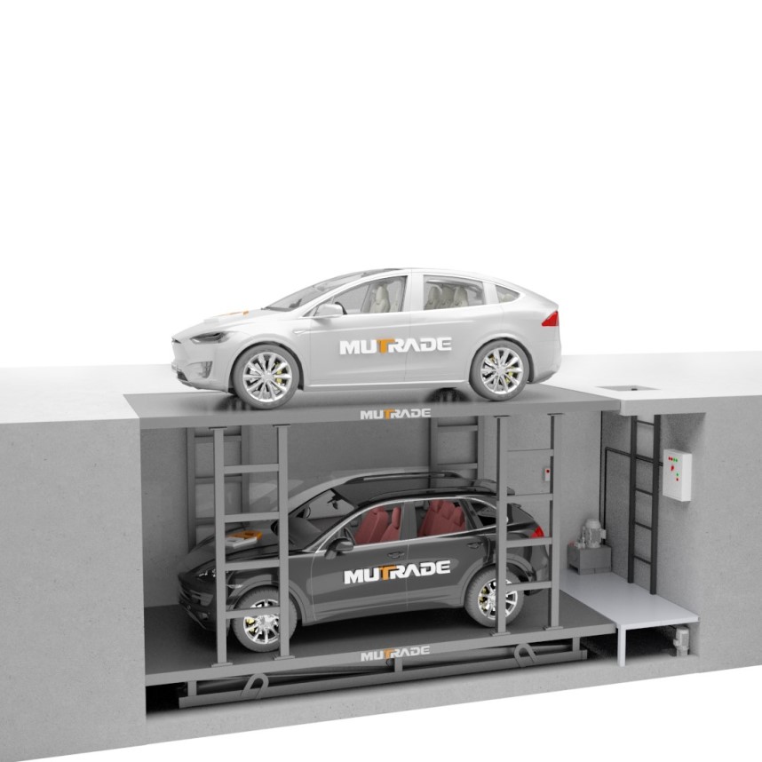
The elevator pit serves as the structural anchor for the entire system. Engineering requirements for the pit floor are stringent. They dictate specific depth specifications that accommodate safety buffers, hydraulic cylinders, and the platform's structural frame when resting at the lowest landing. The base must be perfectly level to ensure uniform load distribution. More importantly, the pit floor and surrounding foundation must withstand massive dynamic impact loads. When a heavy vehicle drives onto the elevator platform, the sudden transfer of weight creates a shock load. This load travels directly through the guide rails and buffers into the pit floor. Structural engineers must detail heavy rebar reinforcement, often using #6 or #8 rebar on tight spacing, to prevent concrete cracking or foundation settling under these repeated dynamic stresses. Soil bearing capacity must be verified through geotechnical testing before the foundation is poured.
Groundwater intrusion presents a severe implementation risk for pit construction. A flooded pit destroys electrical sensors, corrodes safety buffers, and contaminates hydraulic fluid. This leads to total system failure and massive repair bills. Rigorous waterproofing is a non-negotiable requirement. Construction teams must utilize comprehensive waterproofing strategies. You need exterior applied membranes on the foundation walls before backfilling. You must install physical waterstops at all cold joints between the pit floor and walls. Interior crystalline waterproofing treatments that penetrate the concrete matrix provide a final line of defense. Sump pumps are often required by code. You must coordinate their placement carefully to avoid interfering with elevator equipment. They must be equipped with oil separators to prevent hydraulic fluid from being discharged into municipal sewer systems.
Perfectly plumb and square hoistway walls are the prerequisite for a smooth, vibration-free elevator ride. Guide rails must be installed with laser precision. If the structural walls wave, bow, or lean, the rails will require excessive shimming. Over-shimmed rails lack structural rigidity, causing the cab to sway during travel. This misalignment places immense stress on the guide shoes and rollers, leading to premature mechanical failure. General contractors must enforce strict quality control. Utilize laser plumb bobs and continuous surveying to ensure the shaft walls remain within the manufacturer's specified tolerances. This is often less than one inch of deviation over a fifty-foot vertical rise. Any concrete spalling or honeycombing must be patched with high-strength structural grout before the rail brackets are installed.
Material selection for hoistway walls directly impacts both structural integrity and life safety. Construction typically involves either Concrete Masonry Units (CMU) or poured-in-place concrete. CMU construction requires fully grouted cells and precise placement of structural tie-in points for the heavy-duty guide rail brackets. The mortar mix must meet strict compressive strength requirements, and bond beams must be installed at specified intervals. Poured-in-place concrete offers superior strength and smoother wall surfaces but requires meticulous formwork to maintain plumb tolerances. Regardless of the material, building codes strictly mandate 1-hour or 2-hour fire-rated wall assemblies. This prevents the hoistway from acting as a chimney during a building fire. All penetrations for MEP systems must be sealed with approved intumescent firestopping materials to maintain this rating.
Hoistway Material Comparison
Construction Method | Load Capacity | Plumb Control | Fire Resistance | Installation Speed |
|---|---|---|---|---|
Poured-in-Place Concrete | Extremely High | Requires rigid formwork | Easily achieves 2-hour rating | Slower curing time |
Concrete Masonry Unit (CMU) | High (Fully grouted) | Prone to mortar bulging | Achieves 2-hour rating | Faster block laying |
The top of the hoistway requires just as much engineering attention as the pit. Code-mandated overhead refuge space ensures that maintenance personnel working on top of the elevator cab are not crushed against the ceiling if the elevator overtravels its top landing. This clearance is dictated by the speed of the elevator and the height of the vehicle cab. Additionally, structural engineers must design and specify a rated hoisting beam at the absolute top center of the shaft. This steel beam, typically an S-shape or W-shape profile, is mandatory for the initial hoisting of the heavy elevator cab, platform, and machinery during installation. It remains a permanent fixture for future maintenance, motor replacements, or cable changes. The beam must be engineered to support the heaviest single component of the elevator system, plus a safety factor, and must be securely pocketed into the structural walls.
High-capacity vehicle lifts draw substantial electrical current. They require dedicated power supplies that must be coordinated long before drywall is hung. Engineers must specify the correct voltage, phase, and amperage for the main drive motor. This often requires a heavy-duty 480V three-phase power supply with oversized copper conductors to prevent voltage drop during heavy lifts. Coordination is mandatory for the placement of main line disconnects. You must locate these in the elevator machine room adjacent to the strike side of the door for immediate emergency access. The disconnects must feature heavy-duty NEMA-rated enclosures. Furthermore, separate dedicated circuits are required for cab lighting, door operators, and machine room convenience receptacles. Failure to isolate these circuits according to the National Electrical Code (NEC) Article 620 will result in failed state inspections and project delays.
Elevator shafts and machine rooms generate significant heat and require strict climate control to function safely. Building codes frequently mandate hoistway venting at the top of the shaft to exhaust smoke and hot gases in the event of a fire. This prevents the shaft from pressurizing and forcing smoke into occupied floors. These vents are often tied to the building's fire alarm system via motorized dampers. They remain closed for energy efficiency and open automatically upon smoke detection. In the machine room, temperature control is vital. Hydraulic systems are particularly sensitive to temperature fluctuations. Cold environments increase fluid viscosity, causing sluggish operation and leveling issues. Excessive heat can cause controller failure and degrade hydraulic seals. Dedicated split-system HVAC units are often required to maintain the machine room within the manufacturer's specified temperature range, typically between 60°F and 90°F.
Integrating fire sprinklers inside an elevator shaft introduces severe electrocution risks and equipment damage potential. When local building codes mandate sprinkler heads in the hoistway or machine room, electrical safety codes require a complex integration known as a shunt trip system. Heat detectors must be installed adjacent to every sprinkler head. The temperature rating of the heat detector must be lower than the sprinkler head (for example, a 135°F heat detector paired with a 155°F sprinkler head). If a fire occurs, the heat detector triggers the shunt trip breaker. This instantly disconnects all main power to the elevator equipment before the sprinkler head reaches its activation temperature and discharges water. This sequence prevents water from short-circuiting live high-voltage equipment. Coordinating the fire alarm contractor, the sprinkler fitter, and the electrical contractor to sequence this system perfectly is one of the most challenging aspects of elevator MEP integration. You must test this sequence repeatedly before the state inspector arrives.
The choice between a roped hydraulic system and a traction system fundamentally alters the building's structural design. Hydraulic systems utilize a fluid-driven piston to raise the cab. They are highly effective for heavy loads and shorter vertical rises. This makes them popular for two- or three-story vehicle applications. However, they require an adjacent machine room to house the hydraulic pump and fluid reservoir. They also often demand deeper pits to accommodate the cylinder casing. Traction systems utilize steel cables or belts driven by an electric motor and counterweights. They are essential for taller buildings and higher speeds. Traction systems place massive structural loads on the overhead building structure. You must install heavy steel reinforcement at the top of the hoistway to support the weight of the fully loaded cab, the counterweights, and the hoisting machine.
Architects must weigh the spatial trade-offs of different drive systems early in the design process. Traditional hydraulic or overhead traction systems require a dedicated machine room. This consumes valuable square footage that could otherwise be utilized for parking, storage, or rentable space. Machine Room-Less (MRL) technology mitigates this by housing the compact hoisting motor directly inside the hoistway. The motor is typically mounted on the guide rails at the top of the shaft, and the controller is placed in a small adjacent closet. While MRL systems save floor space, they require a slightly larger hoistway footprint. They place all structural loads directly onto the shaft walls and guide rails. Structural engineers must ensure the hoistway walls are designed to bear these concentrated vertical loads without buckling or deflecting.
Modern vehicle lift installations leave zero room for field routing errors. Utilizing Building Information Modeling (BIM) at Level of Development (LOD) 400 is the most effective strategy for detecting physical clashes before construction begins. By integrating the elevator manufacturer's 3D equipment models with the structural and MEP models, contractors can identify conflicts. You can spot interference between elevator guide rails, structural embed plates, plumbing lines, and HVAC ductwork. BIM coordination ensures that electrical conduits do not penetrate the hoistway in prohibited zones. It verifies that structural tie-ins align perfectly with the masonry joints or concrete reinforcement. Resolving these clashes digitally saves weeks of field labor. It prevents the structural compromises associated with core-drilling misplaced penetrations through finished concrete walls.
General contractors must implement a rigorous quality control checklist throughout the shaft construction phase. Verification of shaft dimensions must occur at every floor level during the build, not just upon completion. Embed plate locations must be surveyed and signed off prior to every concrete pour. Once the shaft is constructed, it must be thoroughly cleaned. Construction debris, concrete slurry, and dust will destroy sensitive elevator door tracks and electrical contacts. The GC holds the responsibility for protecting the hoistway and all staged elevator components from weather exposure. If the building envelope is not fully sealed, temporary roofing and moisture barriers must be erected. This prevents rain from flooding the pit or rusting the precision-machined guide rails.
Shaft Construction Quality Control Checklist
Phase | Inspection Item | Tolerance/Requirement |
|---|---|---|
Pre-Pour | Embed Plate Locations | Match approved shop drawings exactly |
Post-Pour | Wall Plumbness | +/- 1 inch over total vertical rise |
Pit Completion | Waterproofing Integrity | Zero visible moisture or seepage |
Pre-Installation | Shaft Cleanliness | Free of all dust, debris, and slurry |
Vehicle lift installations sit at the complex intersection of ASME A17.1 (Safety Code for Elevators and Escalators), local building codes, and municipal fire regulations. Navigating this regulatory landscape requires proactive communication with state or municipal elevator inspectors. The general contractor must ensure all prerequisites are met before the elevator contractor can even begin installation. This includes a dry pit, permanent power availability, and installed hoisting beams. Final inspections are rigorous. The inspector will test the shunt trip integration, fire recall sequencing, and full-load dynamic braking. Failing a final inspection due to a missed code requirement delays the issuance of the Certificate of Occupancy. This holds up the entire building turnover and incurs massive financial penalties.
Request a comprehensive site survey and dimensional audit of your current architectural plans to identify potential hoistway clashes.
Initiate a design consultation with a specialized vehicle lift manufacturer to finalize equipment selection and lock in structural load requirements.
Implement a technical shaft coordination checklist for your general contractor to enforce strict plumb tolerances and MEP integration milestones.
Schedule a pre-construction coordination meeting with your structural engineer, electrical contractor, and fire suppression team to map out shunt trip and venting requirements.
A: Pit depth varies significantly based on the drive type, lifting capacity, and platform speed. Typically, it ranges from 4 to 6 feet. Hydraulic systems may require deeper pits to house cylinder casings, while heavy-duty traction systems need space for large safety buffers. Always consult the specific manufacturer's shop drawings before excavating.
A: Industry standards require extreme precision, typically demanding the shaft walls be plumb within +/- 1 inch over the entire vertical height of the hoistway. Strict plumb tolerances are mandatory to ensure guide rails can be installed securely without excessive shimming, preventing cab sway and premature mechanical wear.
A: Building codes generally mandate a 1-hour or 2-hour fire-resistance rating for hoistway walls. The exact requirement depends on the building's overall height, occupancy classification, and whether the shaft connects multiple fire zones. All joints and penetrations must be sealed with approved firestopping materials to maintain this rating.
A: No. Elevator and building codes strictly prohibit routing non-elevator-related mechanical, electrical, or plumbing systems through the hoistway. Only wiring, conduit, and piping directly necessary for the operation and safety of the elevator itself are permitted inside the shaft to prevent interference and safety hazards.
A: Codes often require a vent at the top of the hoistway to allow smoke and hot gases to escape during a fire, preventing the shaft from pressurizing. Additionally, machine rooms require dedicated climate control to regulate temperatures, ensuring hydraulic fluids maintain proper viscosity and electrical controllers do not overheat.
A: A shunt trip is a critical life-safety mechanism used when fire sprinklers are present in the shaft or machine room. It uses a heat detector to automatically disconnect main electrical power to the elevator equipment just before the sprinkler head activates, preventing catastrophic electrocution and severe equipment damage.





